Register now to gain access to all of our features. Once registered and logged in, you will be able to contribute to this site by submitting your own content or replying to existing content. You'll be able to customize your profile, receive reputation points as a reward for submitting content, while also communicating with other members via your own private inbox, plus much more! This message will be removed once you have signed in.

Jayakumaran S
Members-
Content count
26 -
Joined
-
Last visited
Posts posted by Jayakumaran S
-
-
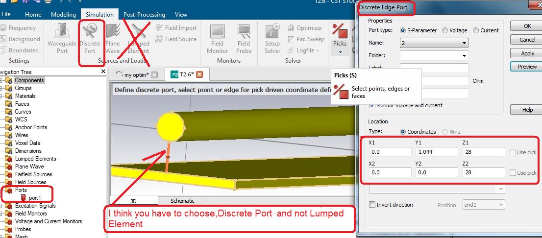
On 2/2/2020 at 4:36 PM, Admin said: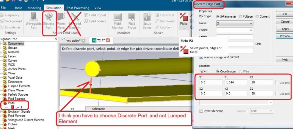
Besides frequency, is there any other reason you choose a discrete port over a lumped port sir?
-
20 minutes ago, Admin said:,,,,where did you get this project from...???
Actually, my friend worked on this design in HFSS and shared the dimensions with me.
He mentioned that some of the values were taken from online sources, while the rest were based on approximations.
1 person likes this -
48 minutes ago, Admin said:,,,must add ground to coaxial cable...!!!!
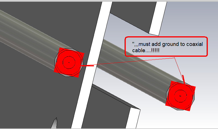
Many thanks for pointing out the need to add ground to the coaxial cable.
Your advice is truly valuable sir.
1 person likes this -
12 hours ago, clanon said:Face select inner+pet+shield+outer edge , then assign wave port (ALL of them should be leveled)
puting a PORT on the END of an ANTENNA is a NO-NO
Thank you so much for the clarification and guidance sir. Your explanation really helped me understand the correct way to assign the wave port.
I truly appreciate your support and time.
-
14 hours ago, clanon said:Still workin on it (good antennas BAD FEED NETWORKS !) I'll upload it if it works give me time
After the simulation is OK on Port impedance Z (should be 50 ohms ) Electronics = Cables= Antennas (50Ohms=50Ohms=50ohms)
I'm glad to have found this website and your support. While I can handle complex designs, I struggle with port assignment and impedance.
I look forward to learning from experienced people like you. I’m truly grateful to you sir thank you.
1 person likes this -
20 minutes ago, clanon said:Those TWO collineal NEED an adapter to SHOW 100 Ohms in the middle (50ohms on coax)
Two identical antennas of 50ohms would give 25ohms in the middle not right
I ran one alone and is promising...

Thank you so much sir, could you please send this corrected design file.
And where i can see the OHM stuff in CST.
1 person likes this -
On 12/9/2020 at 3:46 PM, Admin said:,,, and yet no, this omni antenna is not well sized...
,,, it is for 2.63 Ghz
and this is the reality after resizing...
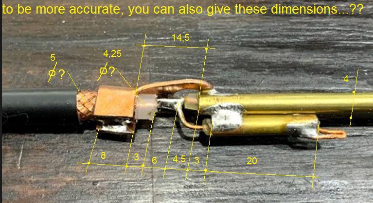
I noticed the simulation includes a connector. Is it necessary to simulate with one?
Also, if the antenna ends with a copper rod, I have assigned the wave port by selecting the rod’s end face. Similarly, for a copper tube, I selected the tube’s face and assigned the wave port.
Kindly confirm if this method is correct.
-
On 5/31/2024 at 8:08 PM, clanon said:you gonna need tubing (aluminum old TV antennas) 10 mm or more...MOST Array aren't omni , metasurfaces are a LIE...VERTICAL FRANKLIN Collineal is the way...BUT MOST I see are folded dipoles with facing on the coax...SO a SIMULATION is NEEDED for ONE DIPOLE and then multiply by at least 6-8 or 10 units and facing COAX should be calculated...for 340 MHZ and 50 mhz bandwith...
Dear Sir,
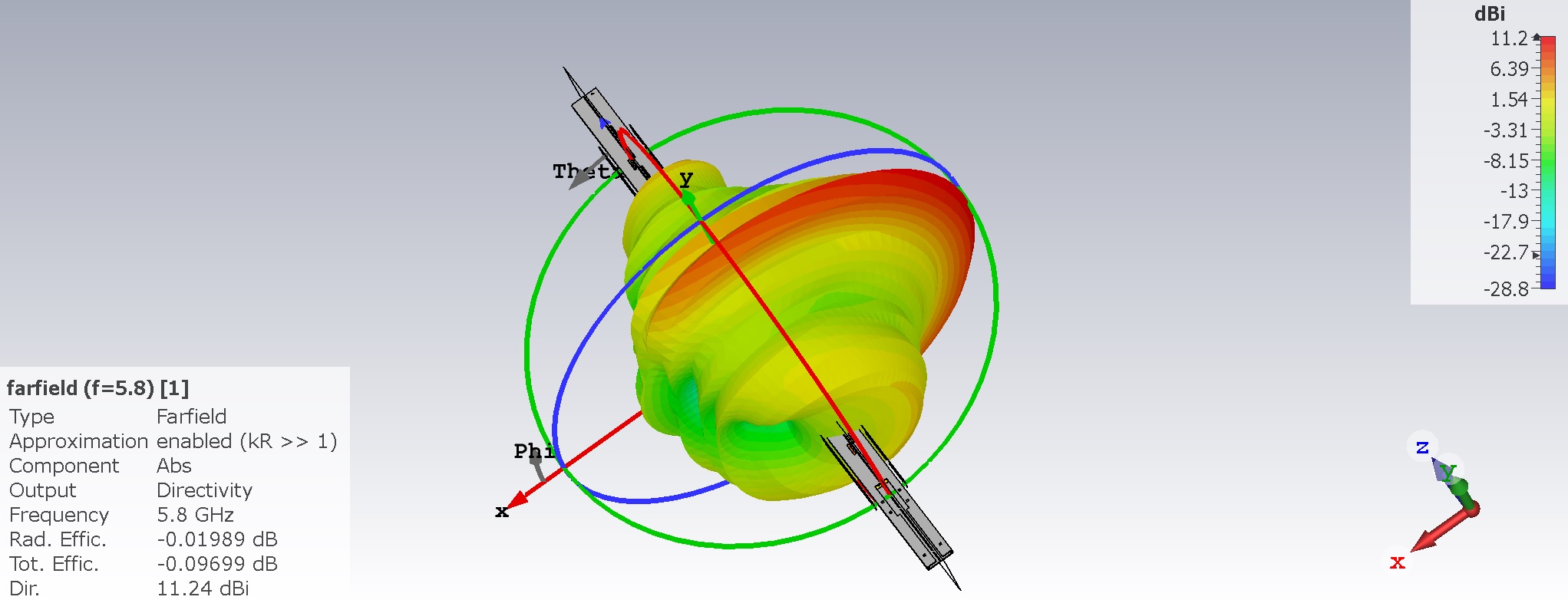
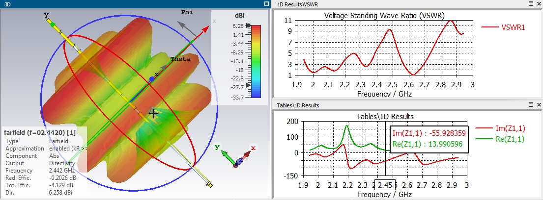
After a long gap, I revisited this website and designed an dual band 2.4GHz and 5GHz omnidirectional antenna based on approximate online dimensions. I attempted to set up a wave port, but encountered meshing issues.
I have attached the design file. Could you kindly help simulate the antenna?
Thanks in advance.
-
On 6/25/2024 at 11:34 AM, Admin said:,,,to make the simulation easier, you can leave air space...!!!
On 6/25/2024 at 11:34 AM, Admin said:,,,to make the simulation easier, you can leave air space...!!!
Dear Sir,
After a long gap, I revisited this website and designed an dual band 2.4GHz and 5GHz omnidirectional antenna based on approximate online dimensions. I attempted to set up a wave port, but encountered meshing issues.
I have attached the design file. Could you kindly help simulate the antenna?
Thanks in advance.
-
On 6/3/2024 at 5:47 PM, Admin said:,,,there are insulating spacers compared to the outer protection tube....!!!
sir iam designing a omni antenna in HFSS, should i include this spacer material or can i give gap(empty space)?, thanks in advance sir.
-
On 12/21/2019 at 1:18 PM, Admin said: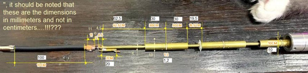
sir what is that white coloured material between the copper tubes? and if that copper tube is hollow how it stand fit by means of that white material?
-
9 hours ago, clanon said:12 dbi omni is doable...what wideband arround 340 mhz...? (Narrow = Wire , Wide = Tube) but you gonna end up close to 5 meters having 44 cm each dipole... a big Tower...for omni...
sir i want slighty wider band(50MHz band width), i did array and metasurface , is there any other option to improve the gain sir.
-
On 5/28/2024 at 9:57 PM, clanon said:OMNIdirectional and high gain are MUTUALLY EXCLUSIVE can not have BOTH...at 340 mhz omni Vertical colineal VEEERY LOOONG could get you 15 dbi...using several meters of wire...
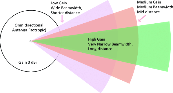
sir i need omni within 500mm length and having the gain of 12dbi what can i do sir, i did array and metasurface , is there any other option to improve the gain sir. Thank you sir for your consideration.
On 5/27/2024 at 10:36 AM, Admin said:,,, with gain of 25-30 dBi,I think is not possible...!!!
thank you for your reply sir, please send any omni directional antenna source img or dwg files for improving the gain atleast 12-15dbi.
-
On 5/25/2024 at 0:53 PM, Admin said:Thanks sir, you are great man.
-
3 hours ago, Admin said:,,,why dwg file...???
so that i can get idea for my reqiured 340MHz antenna, tuning to 340MHz and i'll clear the doubt in port assigning.
-
On 2/19/2021 at 0:31 PM, Admin said:That might be close to reality....
yes sir, i also need the dwg or design files, iam awaiting for your reply sir.
-
34 minutes ago, Admin said:,,, with gain of 25-30 dBi,I think is not possible...!!!
thank you for your reply sir, please send any omni directional antenna source img or dwg files for improving the gain atleast 12-15dbi.
-
On 8/5/2022 at 0:40 AM, Admin said:...yes, but I don't really trust the gain of the antenna..!!!
sir, in our page wifi omni antenna is rare to find, can you fetch and share it with some dwg.files, please sir. thanks in advance.
-
On 3/23/2022 at 6:53 PM, Admin said:,,, maybe it would be interesting to see these...
https://www.lan23.ru/forum/node/340
https://deracahyono.wordpress.com/2011/02/26/isi-omni-built-up-hyperlink-15-dbi-review/
sir i want to improve the omnidirectional antenna at 340MHz with gain of 25-30dBi, is it possible? , can you send any design images or design files that match with my spec, please help me sir.
-
On 5/25/2024 at 0:53 PM, Admin said:Thanks sir, but i only know English, any site for English ? please sir
-
On 2/27/2019 at 5:56 PM, Admin said:A directional antenna 699 - 2690 MHz, 2x2 MIMO SMA
MikroTik mANT LTE 5o is a Omni-directional antenna, designed especially for use in radio and television LTE. Perfect for wAP devices-LTE and LtAP. Is characterized by a profit of 5 dBi has been fully adapted for use outdoors. This will improve the quality of the LTE connection (hanging the antenna outside of the building eliminates additional interference, which bring in the wall). The operating frequency range is from 699 MHz to 2690.
The offered product uses a double polarization, thus, full use of 2x2 MIMO transceivers (such as the R11E-LTE). Due to the fact that the used antenna is Omni-directional it should not cause problems even to those people who are not familiar with similar technology (you do not need wizować antenna). The kit includes the clamp for mounting on a pole.
Dear sir, is there any wifi omnidirectional antenna below 500MHz with high gain in our page?
-
dear sir, i knew HFSS, is there any site for HFSS like this ? please suggest me sir.

in Modeling antennas
Posted
Understood, Sir. Thank you for the clarification.