Register now to gain access to all of our features. Once registered and logged in, you will be able to contribute to this site by submitting your own content or replying to existing content. You'll be able to customize your profile, receive reputation points as a reward for submitting content, while also communicating with other members via your own private inbox, plus much more! This message will be removed once you have signed in.

swarg_eu
Members-
Content count
38 -
Joined
-
Last visited
Posts posted by swarg_eu
-
-
Your cable (connectors) seems to be badly assembled (happens to the best, there is usually a QC to avoid this), the central pin has 191,8 ohm !!!!!
It should tend like the other conductor to 0 ohm!!
and check that additionally, you don't have a problem with SMA to RP-SMA
-
1. it depends on the cable, for example, the cable has a loss of 0,5 dB/m multiplied with the 10m gives 5dB of signal loss the 7dBi antenna acts now as a 2dBi antenna
2. no TV and WIFI are at different frequencies and a TV antenna is not optimized for 2,4 GHz
3. no it can't, the power of the USB dongle is not high enough to cause any damage due to a mismatch
4. depends on the cable (check the cable specification, the type is usually written on the cable or post a picture of the cable). 2,4 GHz is not that sensitive to small mistakes, make sure that you don't have a short circuit
5. no you don't need a shielding on the USB modem, 21 dBi make sure that the antenna is for 2,4 GHz
1 person likes this -
1. the ground of the antenna needs to be at the defined position to get a proper radiation pattern and impedance matching (mount it on a separate horizontal arm)
On 12. 12. 2021. at 10:44 AM, Shabra said:

2. the parabolic grid antenna is made for a dipole (you don't use the full reflection area of the grid), you reflect only one part of the polarised wave (-3dB for TX and RX, MIMO is not gonna work in this particular case)
an offset satellite dish is a much better choice for a reflector, kip in mind that there is a polarisation change after a reflection (SISO system limitation)
3 people like this -
If your goal is to get to 15GHz and more you are using the wrong connector.
You need an SMT edge connector (I would prefer a 2.92mm connector), lowers the problem with ground
Why did you cut open all metal layers? There is no need for that it only introduces unwanted effects.
1 person likes this -
Expanded Polystyrene er 1,02-1,04 (99% air, water-resistant...)
end of page 4
1 person likes this -
11 minutes ago, Admin said:swarg_eu,You can design such a divider...???
that not a problem,
but depending on the frequency a 90 deg hybrid or a ratrace is a better solution
-
it depends on how you look on the splitter/combiner
- splitter, 2 output ports with a 3dB "loose" compared to the input
- combiner the output has a 3dB "gain" compared to the 2 input ports (assuming the phase and amplitude match)
the question is actually what you do with the splitted/combined signal
in the case of an antenna, the feeding network for the patches splits the power while TX and combines the power while RX
the TX antenna gain and the radiation pattern is a result of the superposition (amplitude and phase) of the patches radiation
the RX antenna gain and pattern are the results of the combined patch (pattern) signals (amplitude and phase)
in the case of a passive antenna, the feeding network is the same for TX & RX resulting in the same pattern for TX & RX and doubling the patch count increases the antenna gain by 3dB (combiner/slpitter)
2 people like this -
On 27. 10. 2020. at 6:11 PM, clanon said:Losses...?
(besides Dielectric , tan loss)
for what?
-
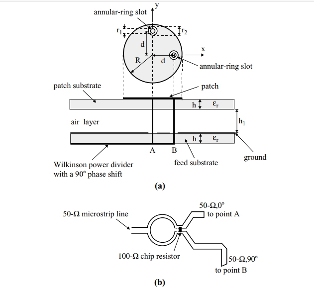
for this type of antenna, a simple power splitter is not a solution (no phase shift between ports)
the patches need to be driven with a 180 deg phase shift, otherwise, there will be no main lobe in the radiation pattern (in its place will be a zero)
Therefore it uses a transformer (wire loop) that transforms the single-ended (asymmetric) to differential (symmetric, 180 deg phase shift) port
the rest of the PCB traces (GND below) ensures a proper impedance match
2 people like this -
 2 people like this
 -
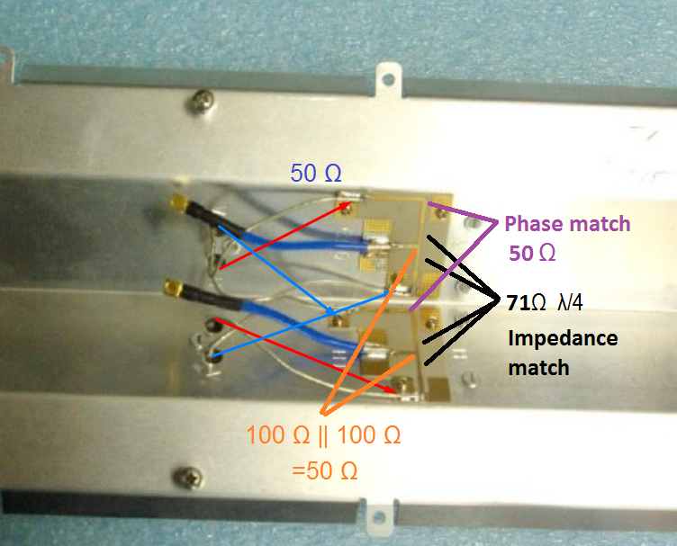
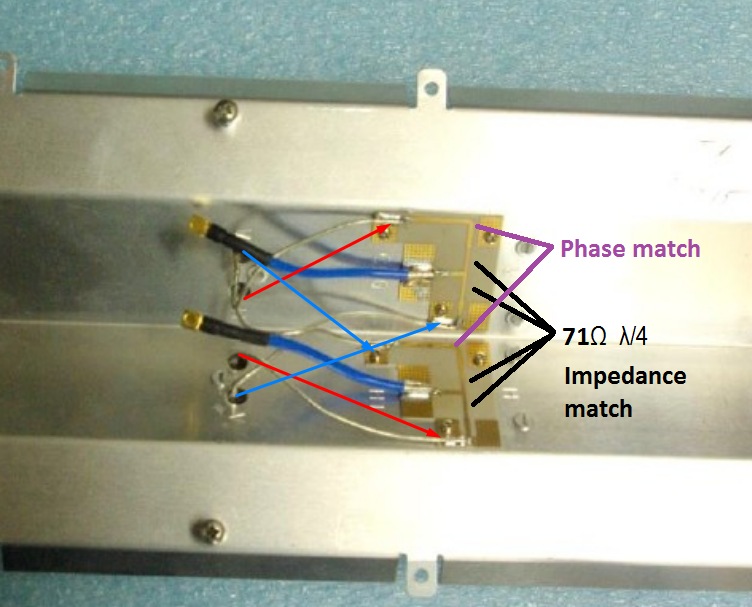
everything else is 50 ohm
 1 person likes this
 -
that is a power splitter (impedance matching)
2x H pol. on one splitter
2x V pol. on the other splitter
2 people like this -
there is a problem:
your antenna is used to RX and TX (TDD, FDD...), and putting a PA or LNA can benefit only TX or RX the other one gets attenuated
the devices have usually an RF front end IC that switches between PA and LNA mode based on control pin voltage ................. (pain in the ass to manipulate)
checkup list:
check that the KIP9-1700/2700 antenna is in the focus of the parabolic dish
the dish is correctly oriented (not a side lobe)
measure the cable & antenna (if you have some equipment), there's maybe water inside the cable...
Easy improvement:
get the router as close to the antenna as possible (5 meters more of ethernet cable has a lower impact on the connection than 5 meters of coax)
Spend money:
get a router that is integrated with the irradiator for example Kroks Rt-Pot sHw DS
get a bigger parabolic dish
3 people like this -
draw me a basic schematic of what you are planig
antenna impedance, source impedance ...
-
Something that you can build by your self
 1 person likes this
 -
the important thing isn't RSSI but SNR
by rotating the antenna for 45 deg, you RSSI dropped bay 3dB but you SNR increased
you seem to be a victim of CSMA/CD & CSMA/CA
there are maximum 14 (Japan2) channels on 2,45 GHz WIFI and there is someone on the same channel
Get a directional antenna ~18 dBi, with some luck the interfering signal is not in the direct line between you and the AP.
If needed with the 18dBi antenna, you have some space to get rid of the negative effects of the CSMA
by putting a 5~10 m long cable to attenuate the interference to a level where the CSMA won't react (it won't stop the transmitting, package drop)
2 people like this -
on the 75 ohm line, the radius is 7 mm, 3 mm from the end of the PCB
6 mm long line with a cut in the middle of 0,4 mm to solder the 150 Ohm resistors
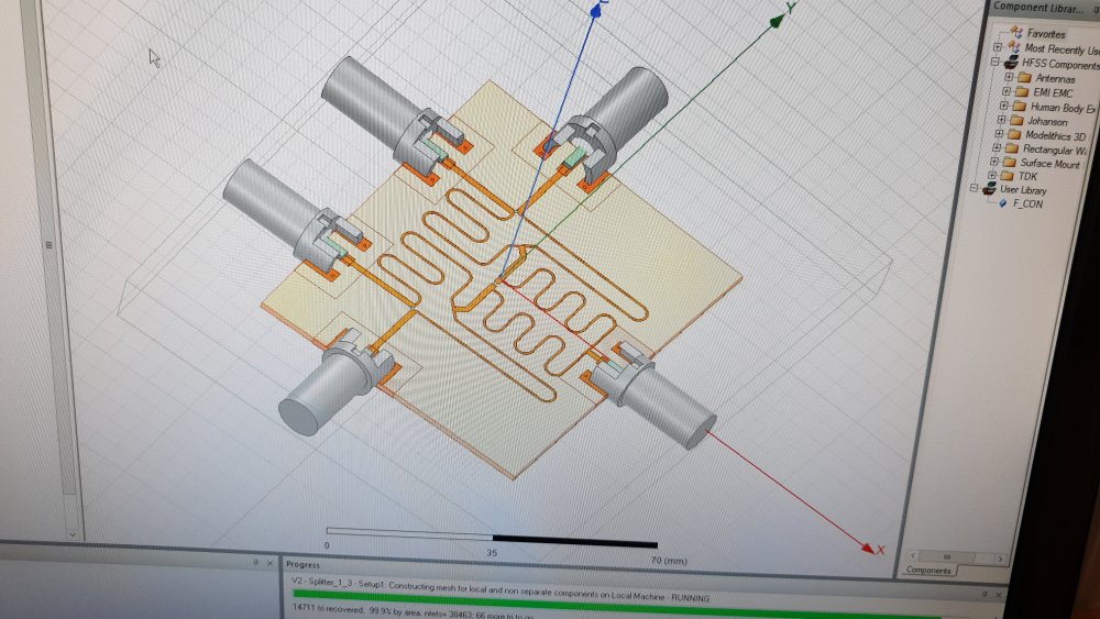
All 3 splitters have the same dimensions:
the radius on the transformer lines is 2,5 mm and the axial distance before the bending (from 75 Ohm line) is also 2,5 mm
the axial distance in the Wilkins splitter is 11,28 mm between the centers of the two radius bends
the axial distance of the transformer lines is 2,88 mm (near the 150 Ohm resistor)
The horizontal distance between the two spitters is 25 mm
75 Omh line 1,2 mm
transformer line 0,48 mm
1 person likes this -
-
that no problem
waths the frequency range?
-
yes, I would choose v2
-
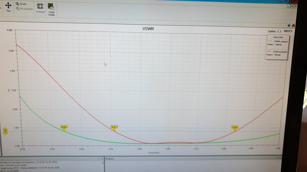
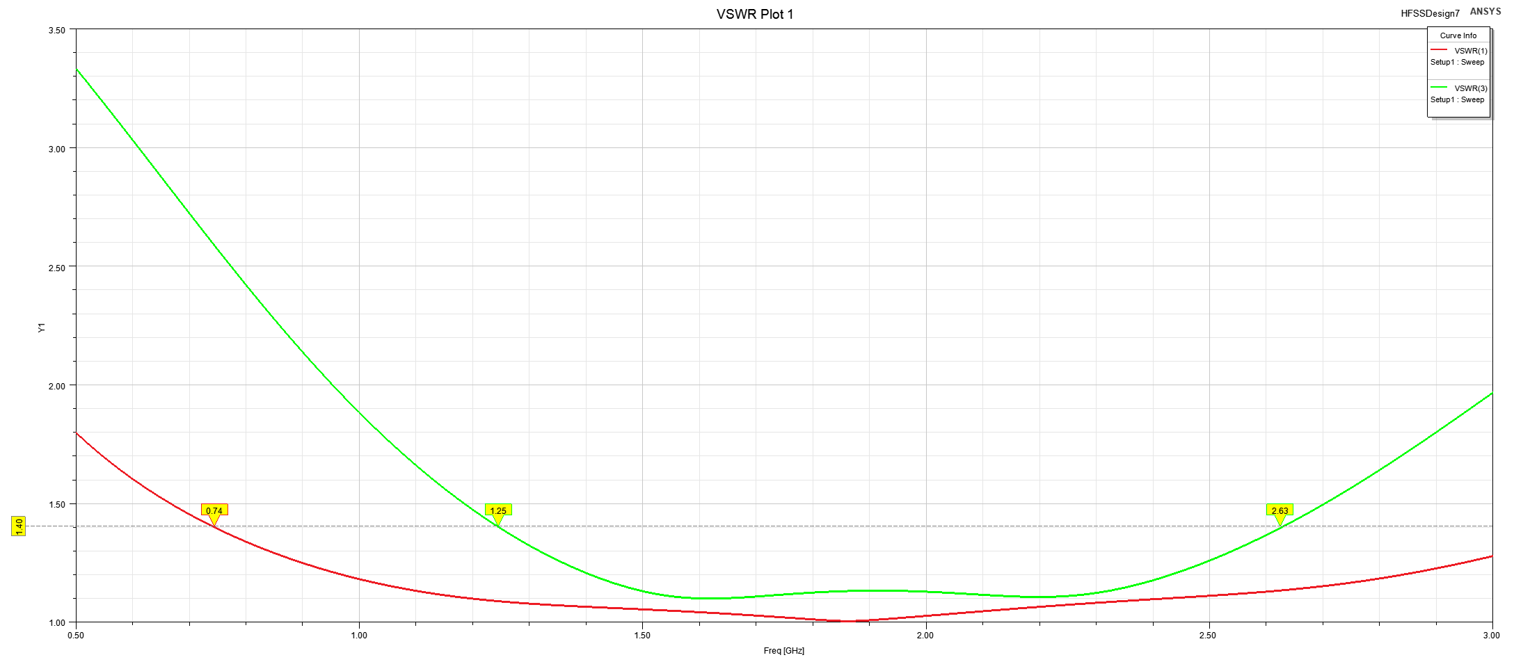
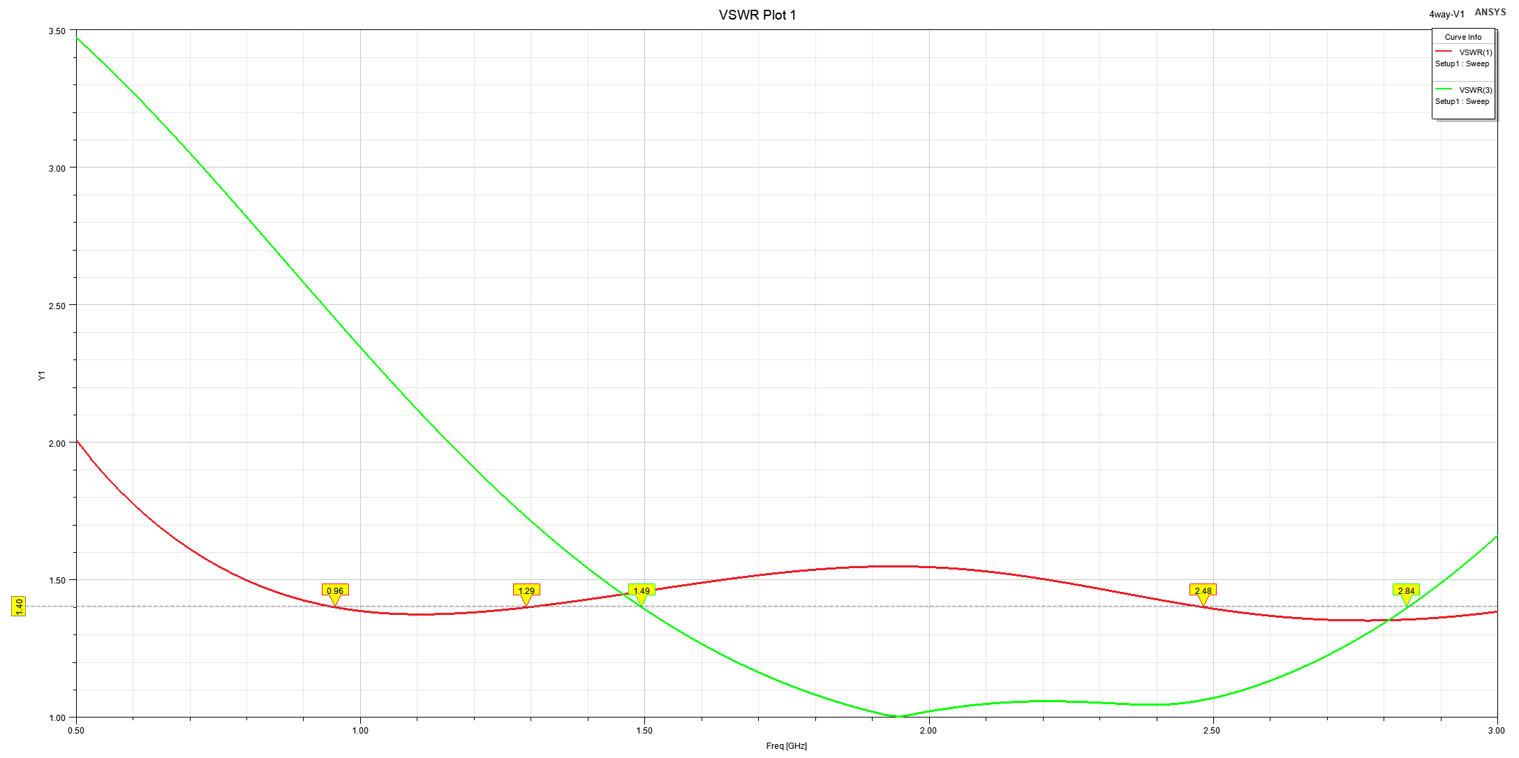
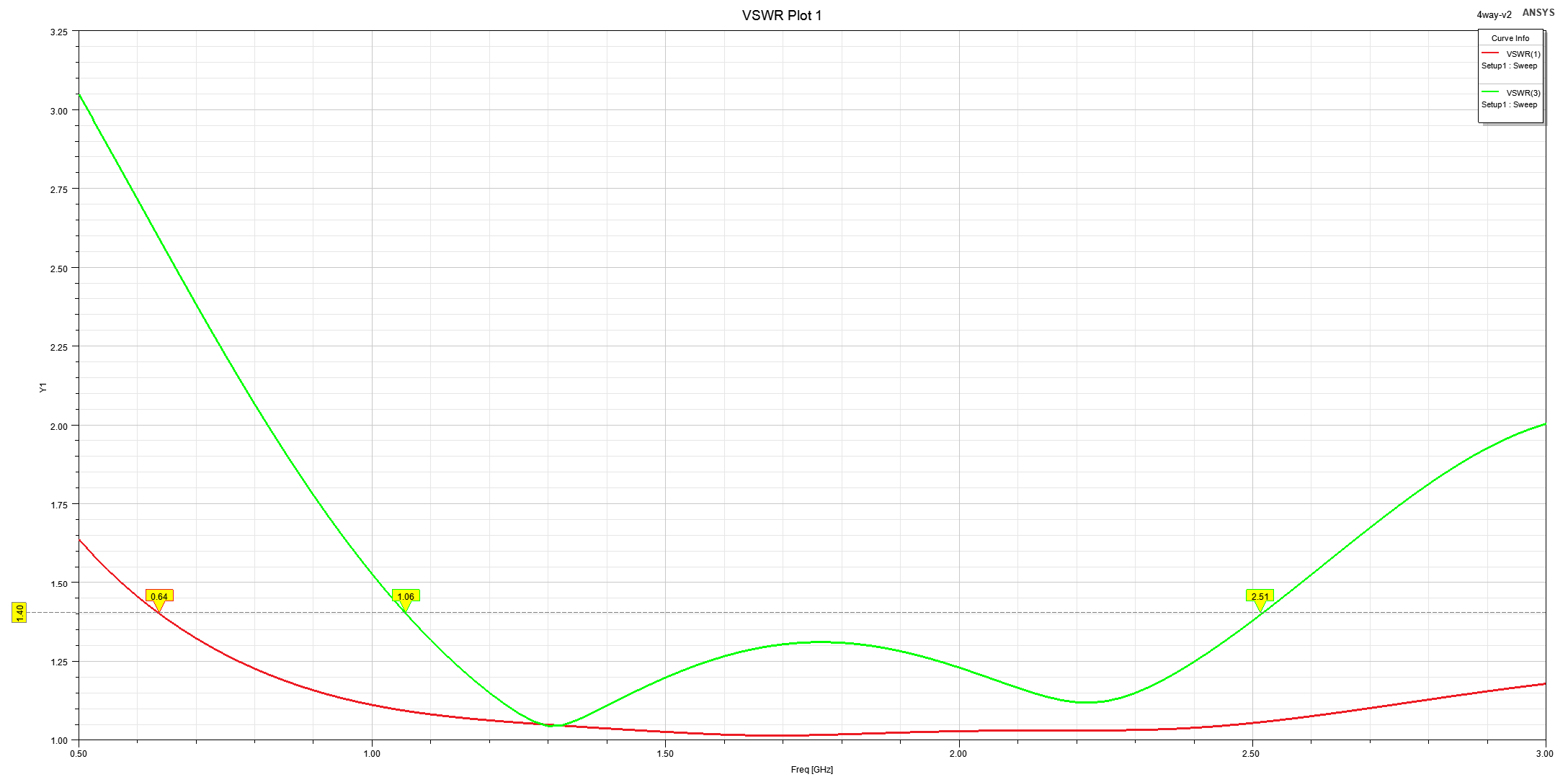
finally got the time for the splitter
version 1 - a combination of Wilkinson and impedance transformer
isolation >10 dB between the 4-antenna ports

version 2 - Wilkinson (the 50 Ohm line between the splitters is long and introduces some side effects in S33)
isolation > 20dB between the 4-antenna ports
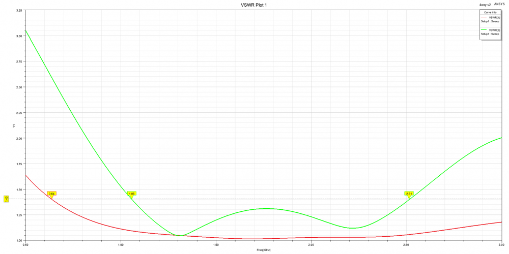
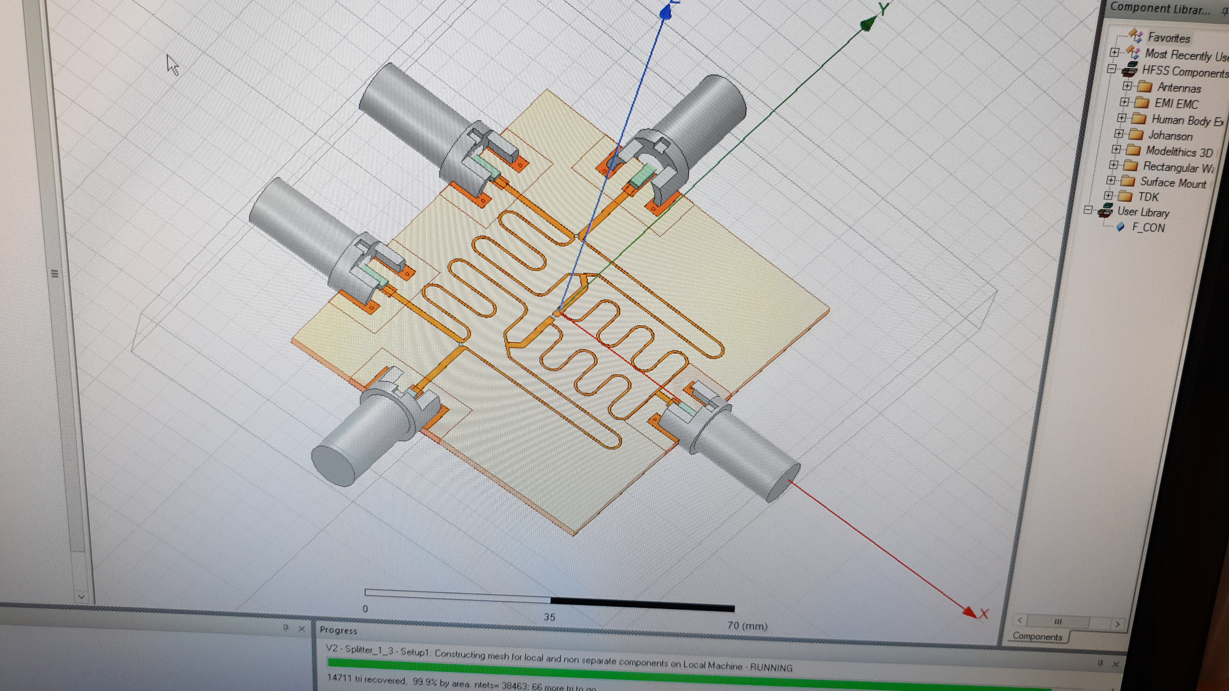
for both versions, the GND VIA connection is modeled as a solid in the substrate (faster simulation), port 1 antenna input port 3 combiner output
3 people like this -
75 or 50 ohm system?
2 or 4 way splitter?
Is FR4 1.6 mm ok?
1 person likes this -
Yes the length of the transmission line needs to adjusted
https://www.microwaves101.com/encyclopedias/wilkinson-power-splitters
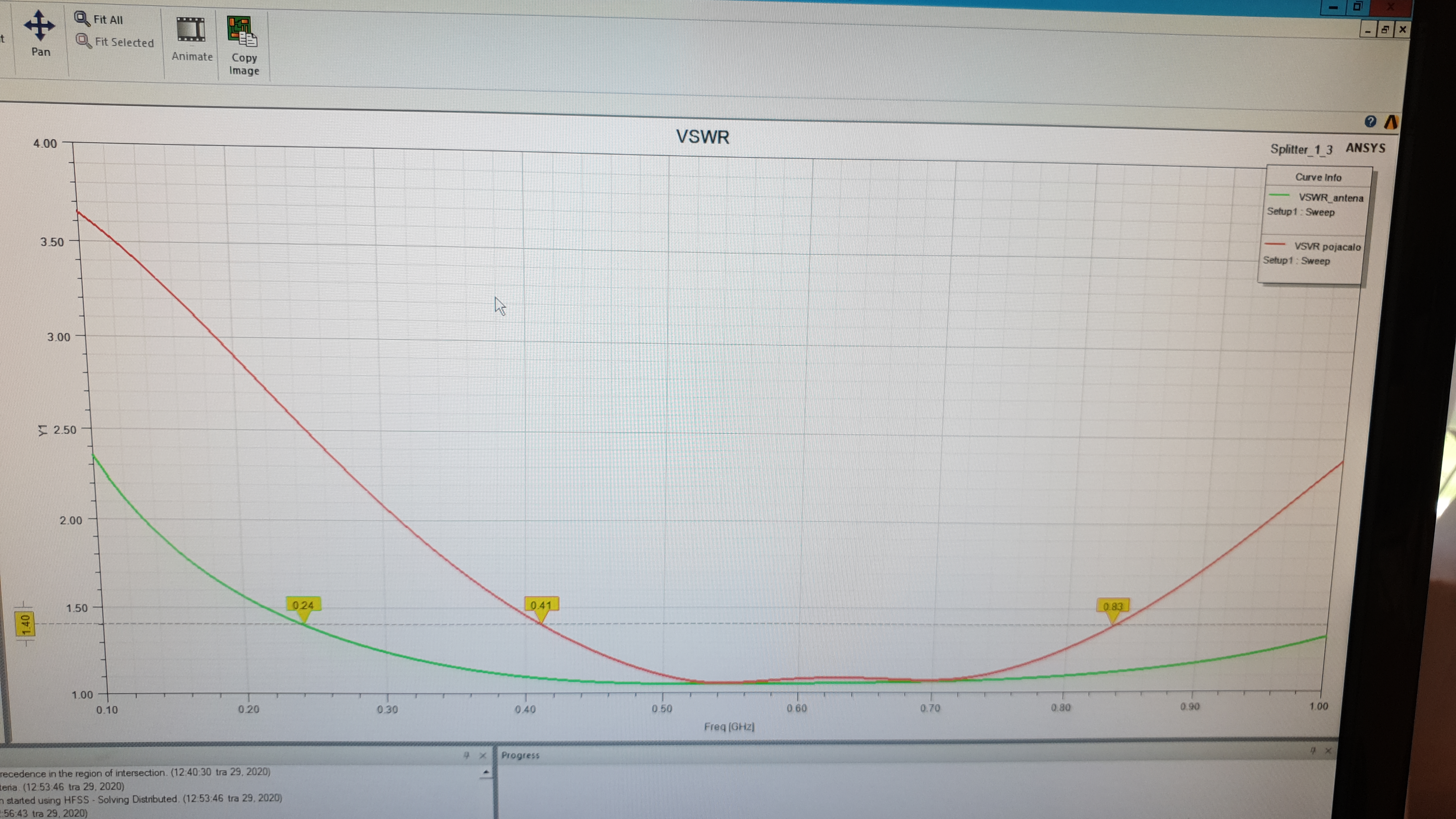
The simulation results for the DVB-T2 splitter
 2 people like this
 -
Combined via 3 x wilkinson splitter
2x antenna on wilkinson
2x wilkinson on wilkinson
Its just added 6dBi gain by combining the 4 antennas to a 2x2 array
1 person likes this
in Buy / Sell / Exchange
Posted
There are 2:1 4:1 combiner, filer, LNA separately and the 4:1 filer and LNA on single board