Register now to gain access to all of our features. Once registered and logged in, you will be able to contribute to this site by submitting your own content or replying to existing content. You'll be able to customize your profile, receive reputation points as a reward for submitting content, while also communicating with other members via your own private inbox, plus much more! This message will be removed once you have signed in.

swarg_eu
Members-
Content count
38 -
Joined
-
Last visited
Posts posted by swarg_eu
-
-
If you are in a place with low RF exposure and there is los this is a good choice.
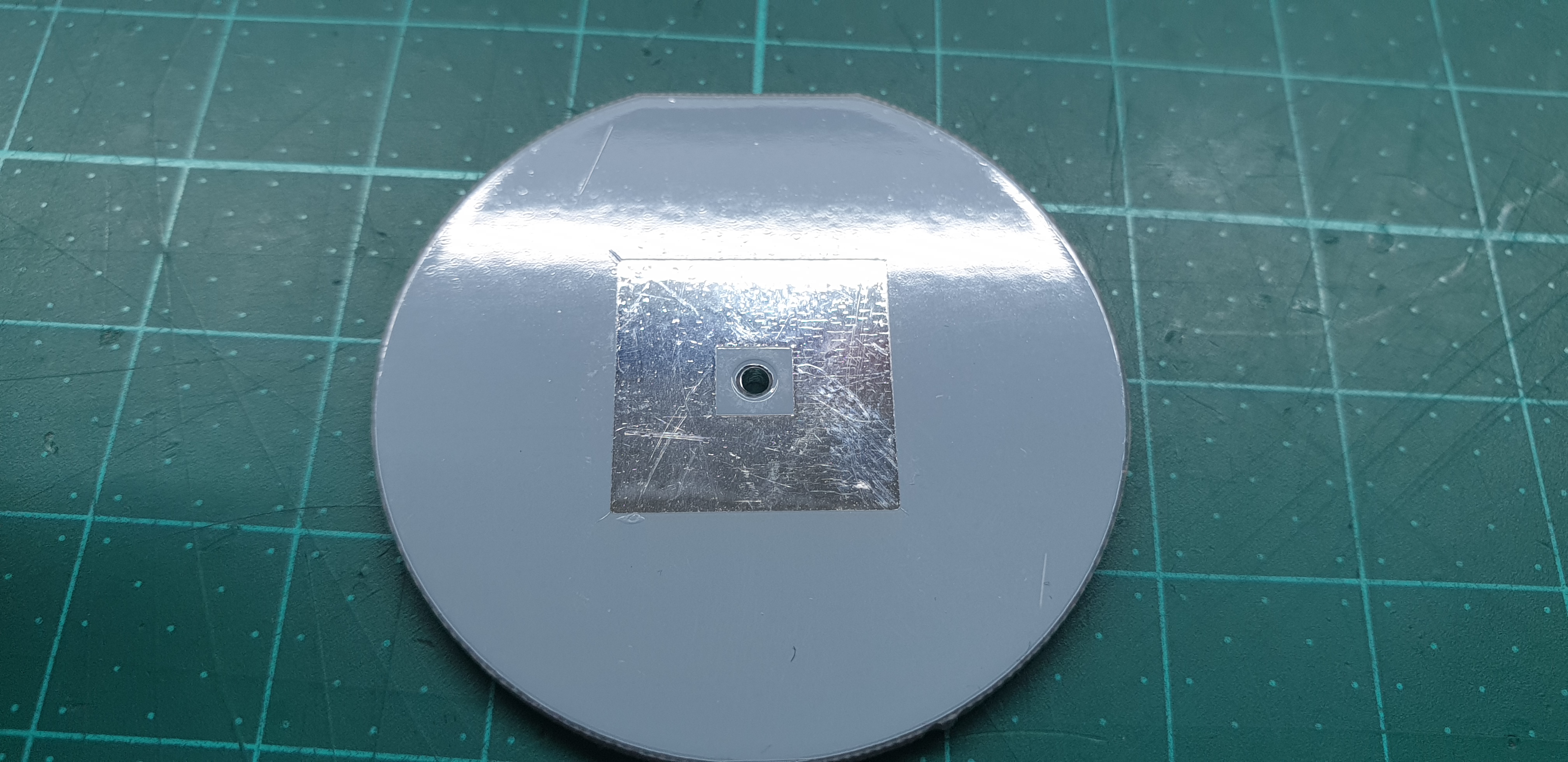
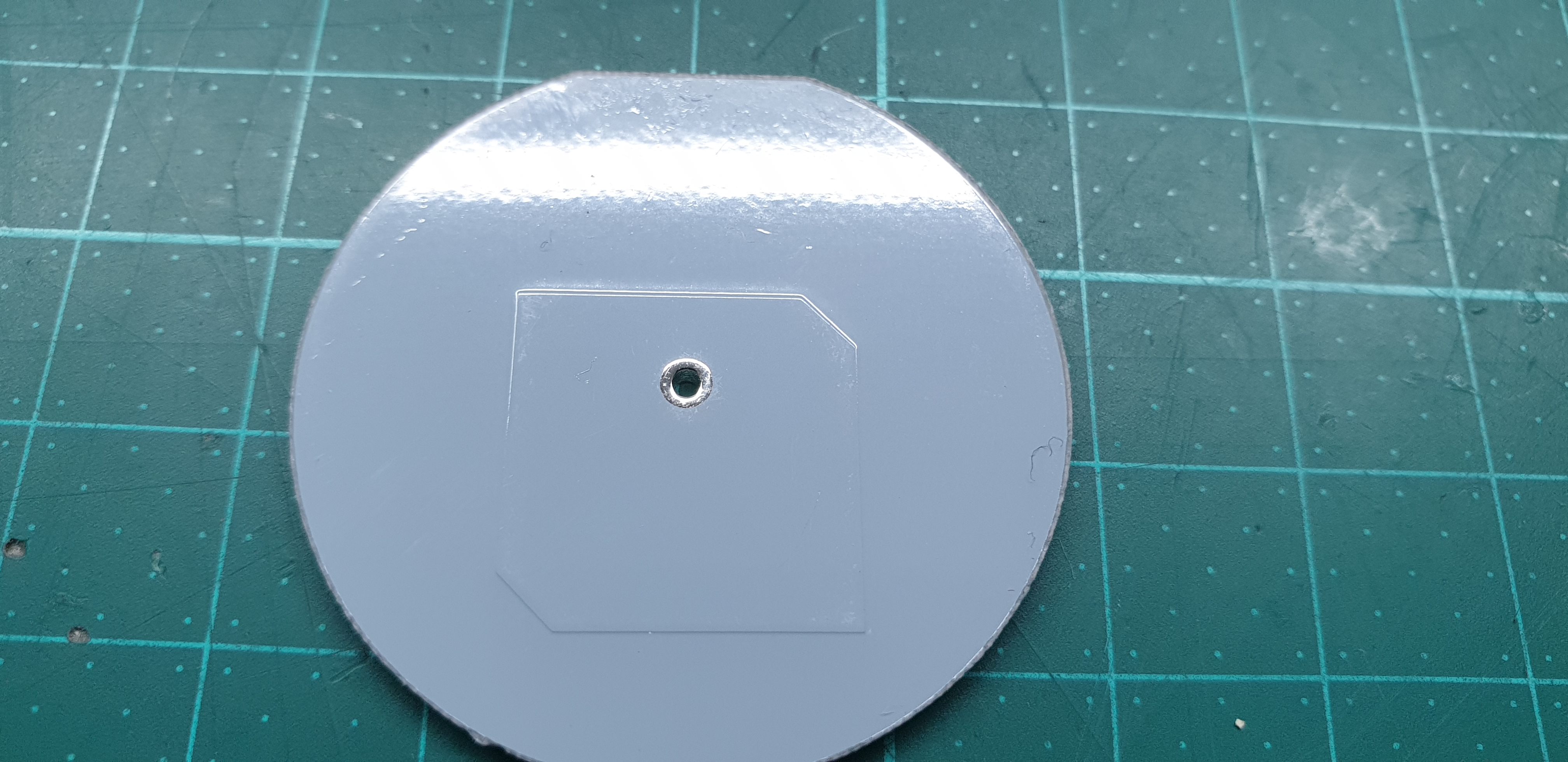
If its easier for you can change the reflector to a disk with a bit bigger radius.
Note that in the 802.11 standard the speed is actually affected by the weakest signal of a active client on the AP.
If you are in a place with higher RF exposure an antena with more gain (additional directors) and an attenuator (long cable) to increase the noise floor for avoiding the CSMA interrupts in 802.11 is sugested
-
Isn't the ~10dBi antenna gain enough for the 500m ?
What is the problem?
-
Put it on a 60 cm offset parabole
1 person likes this -
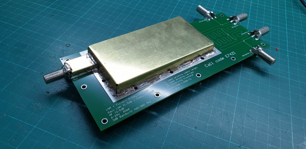
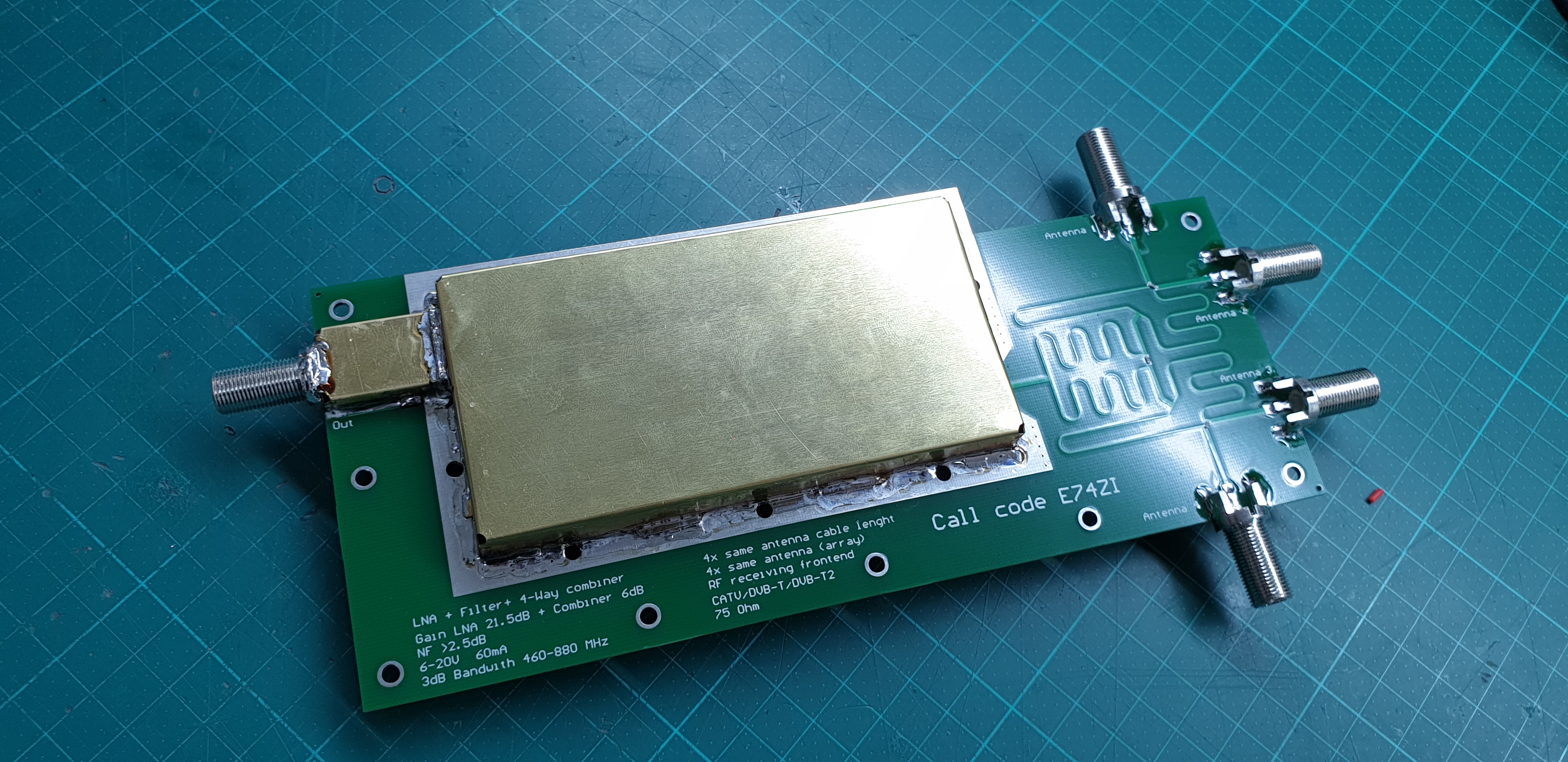
Selfmade RF frontend for Video signal (Analog, DVB-T, DVB-T2, CATV) amplification in a 75 Ohm system.
The RF frontend contains the following building blocks:
4-Way Wilkinson power combiner - combines the signal from 4 antennas (~6dB gain)
bandpass filter - eliminates the interfering radio signals (FM...)
low noise amplifier with a voltage regulator - for sensitivity improvement (~21dB gain, NF~1dB )
Interconnections:
4 F type connector 75 Ohm inputs (antenna)
1 F type connector 75 Ohm output (receiver side), requires a bias voltage in the range of 6-20 VDC and ~60 mA (for example: ZS300 antenna power injector )
Technical data:
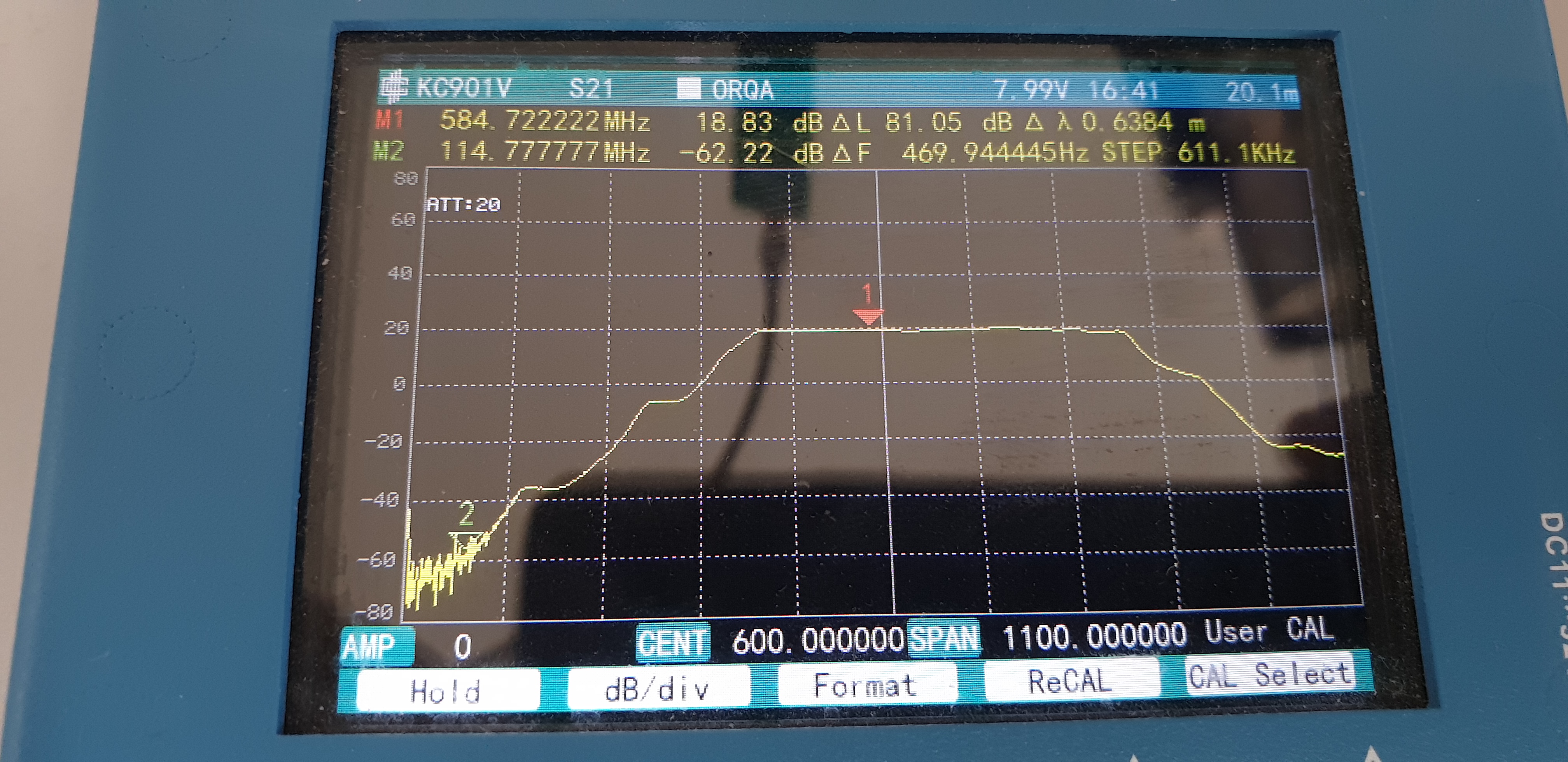
Frequency range from ~460 to ~880 MHz
Noise figure >2,5 dB (including insertion losses)
Gain <25 dB (including insertion losses and combiner gain)
P1dB ~19dBm
Max Pin 17dBm
Size ~250x120x25 mm
The use of this RF frontend is recommended in one of the following scenarios:
the picture is pixelated but you are already using a high gain antenna and amplifier
you are in a high power RF environment, Amateur Radio, FM radio is attenuated by more than 80dB ...
you want to combine the signal from multiple directions to a single cable (signal quality will/can be reduced)
Basic knowledge in antenna (phase) arrays is recommended to exploit the benefits of the RF frontend.
Protective housing not included.
Antennas not included.
Power injector not included.
Coax cable not included.
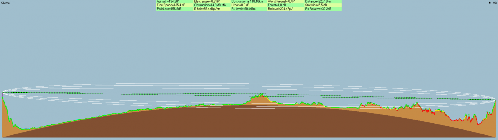
Test results (scenario with a pixelated picture and high power RF environment)
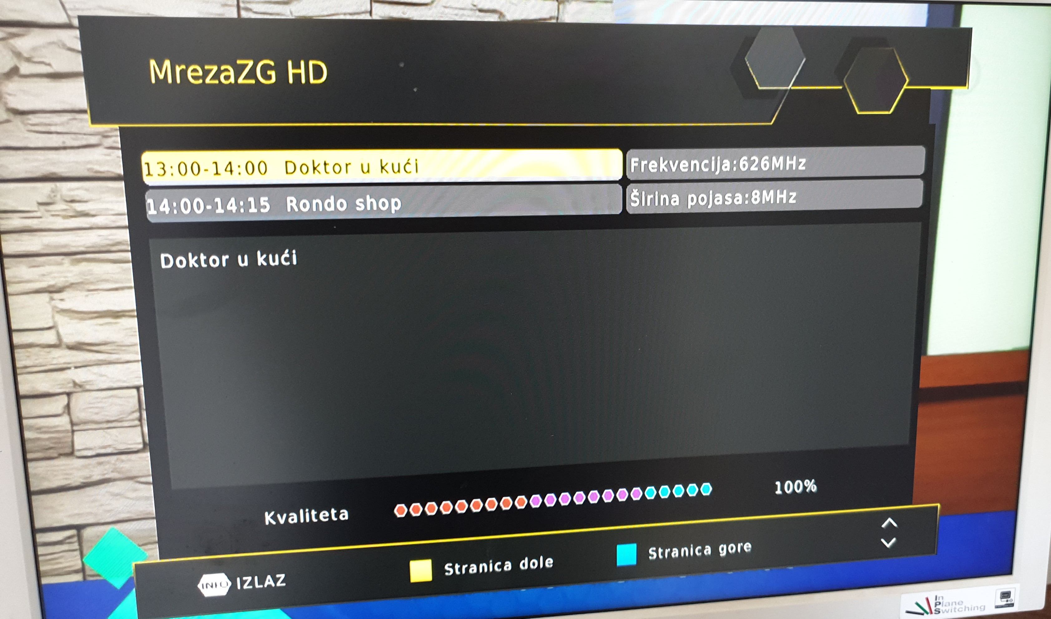
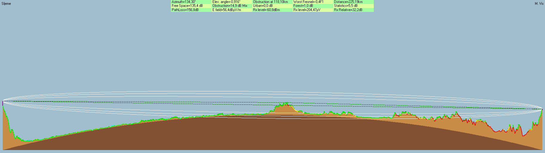
DVB-T2 Transmitter side cordinates 45,89938 N; 15,94786 E;
DVB-T2 Reciever side coordinates 44,47105 N; 17,97297 E;
Link distance ~225 km, no line of sight.
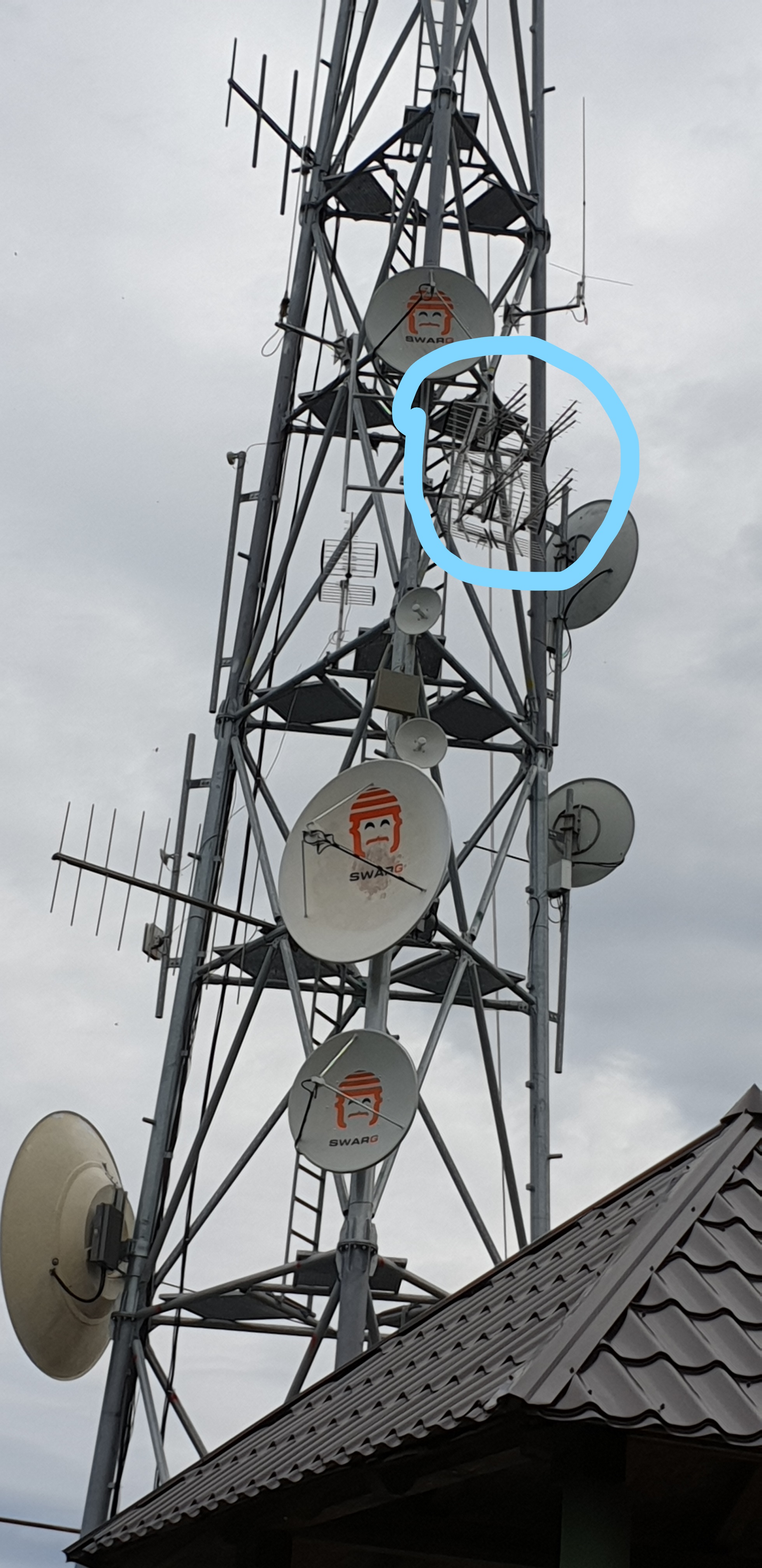
Receiver side 2x2 antenna array with Triplex Loga Iskra P-47N (without an amplifier, marked on radio tower picture), connected with ~1m RG-6/U coax cable (length variation between antennas <1cm) to RF frontend.
Received signal strength (SNR) above the threshold including fading effects (SNR range 29-37 dB).
Successful elimination of interfering radio signals (see measured transmission response) on the receiver side (4 FM station with 400 W ....)
Free worldwide shipping with DHL.


 4 people like this
 -
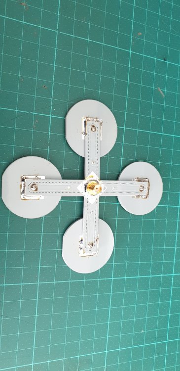
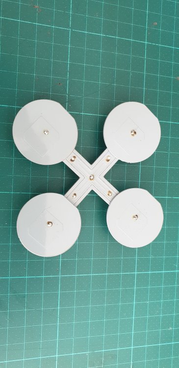
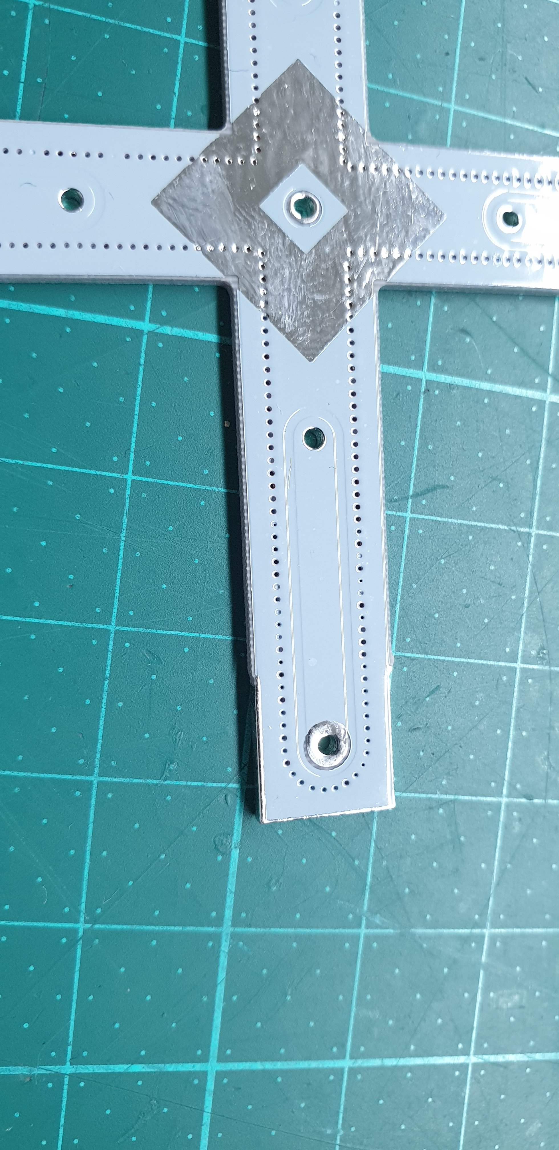
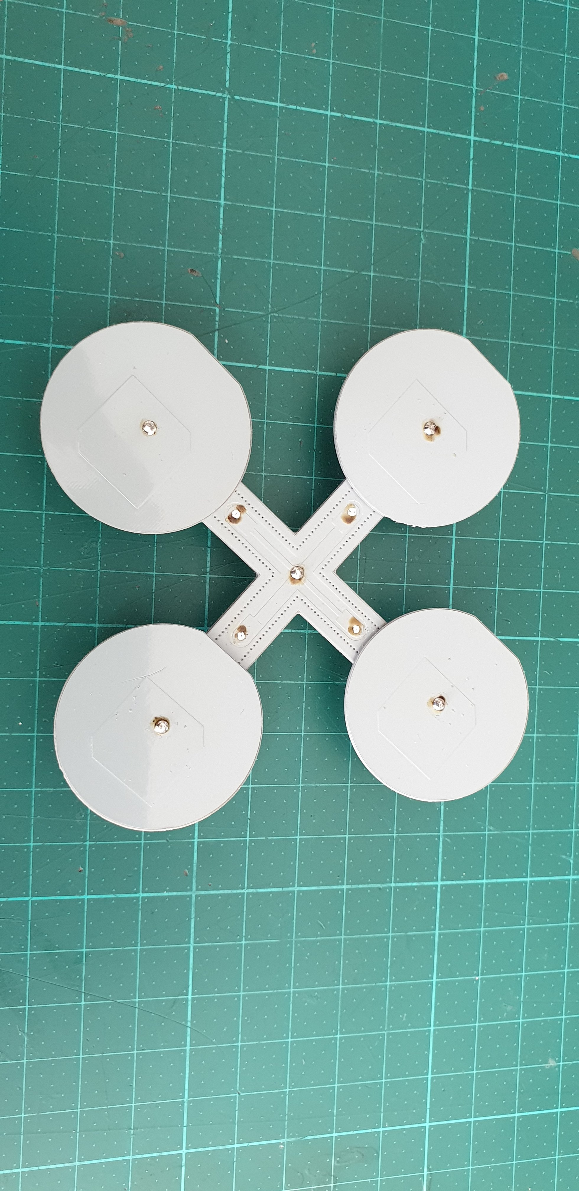
Is the bottom of the patch only GND in the smal part like in the figure ?
Extend the GND to the edges of the PCB
-
-
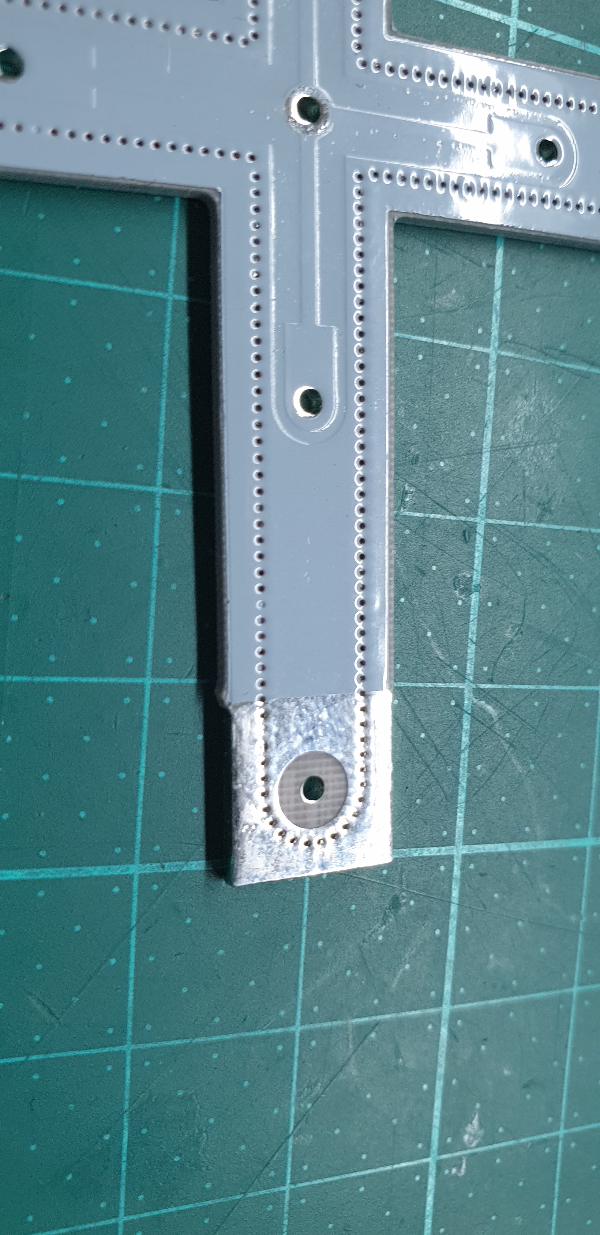
15x15mm , the arm is also plated edge at the end
-
-
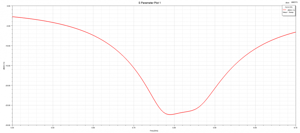
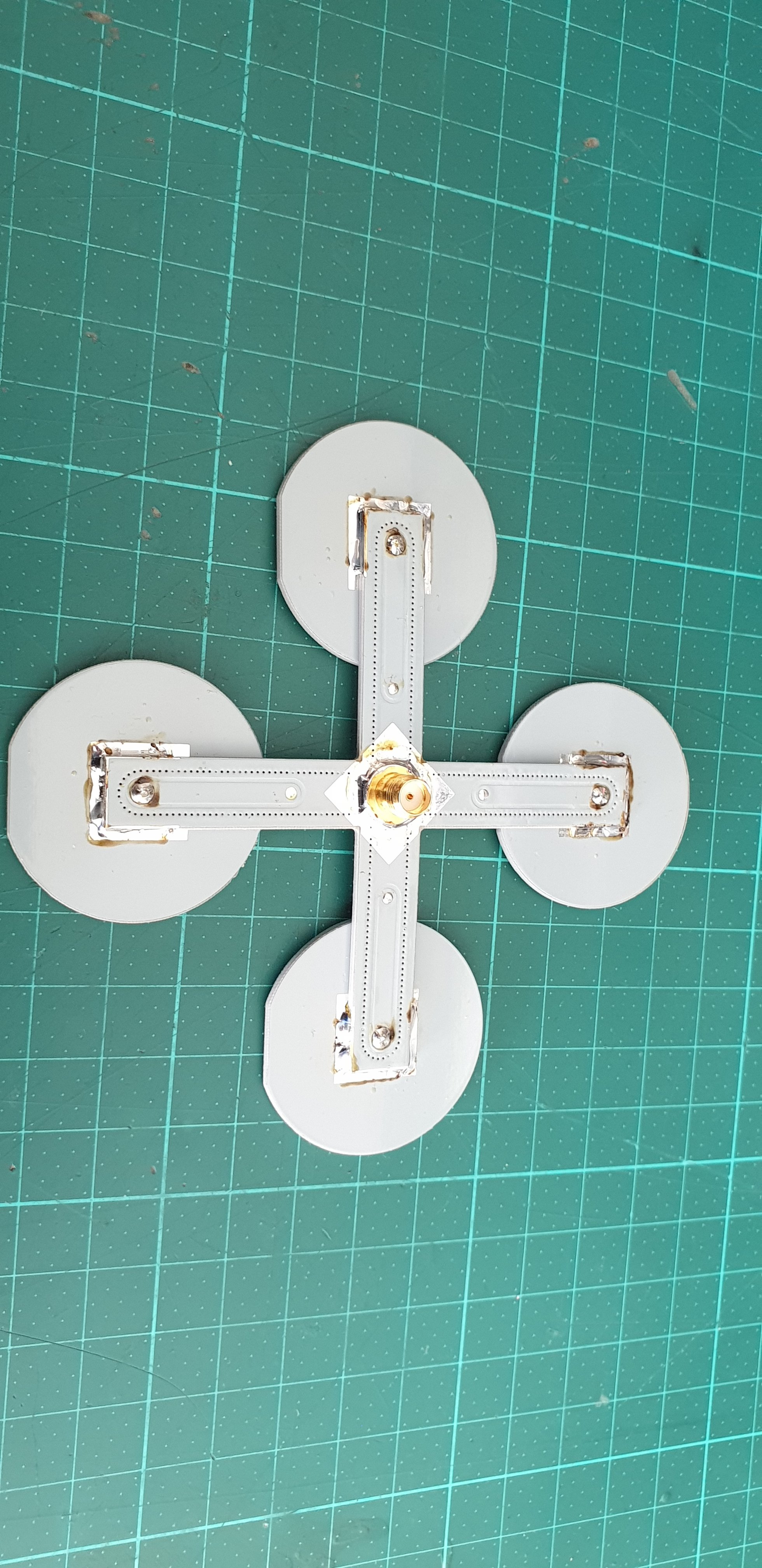
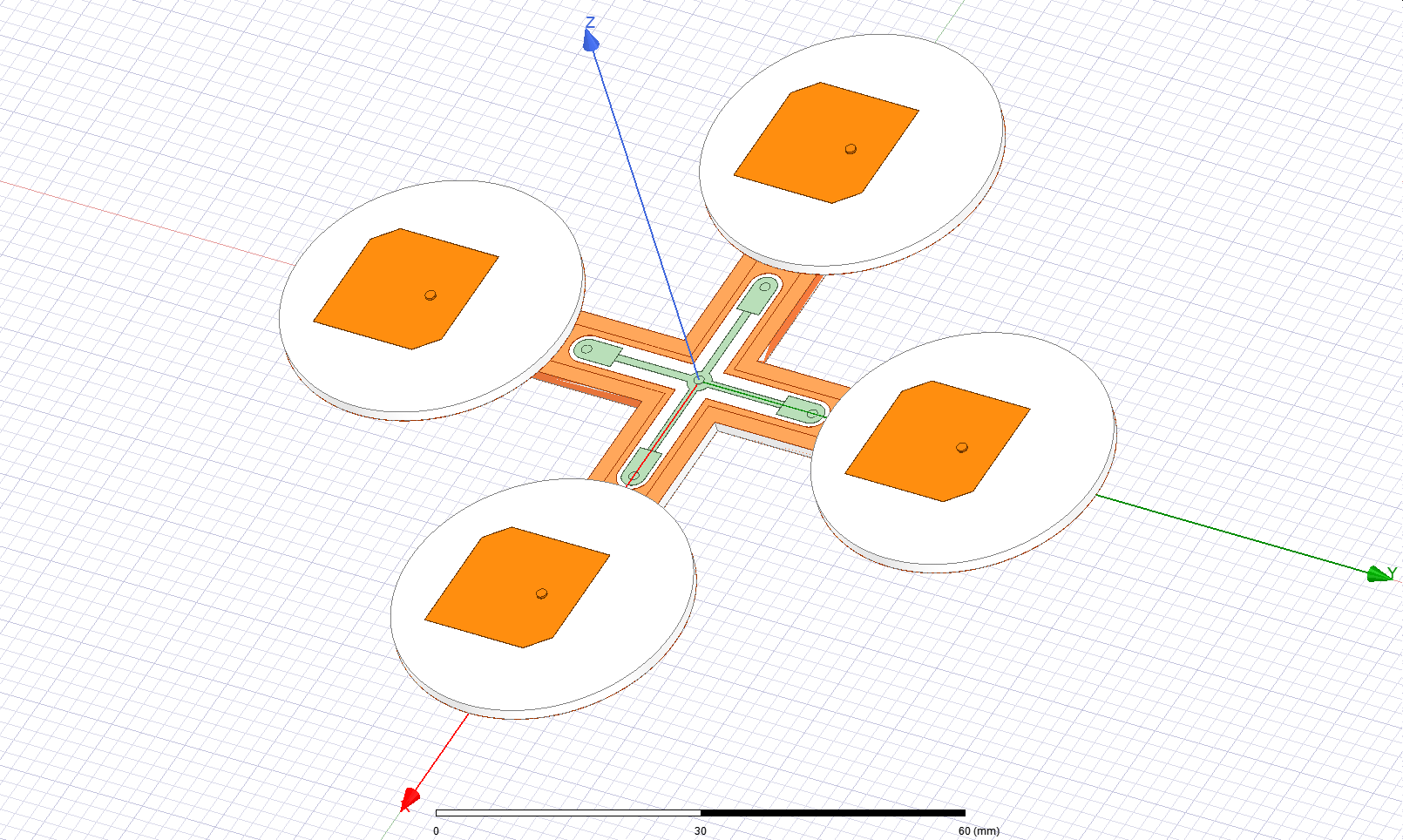
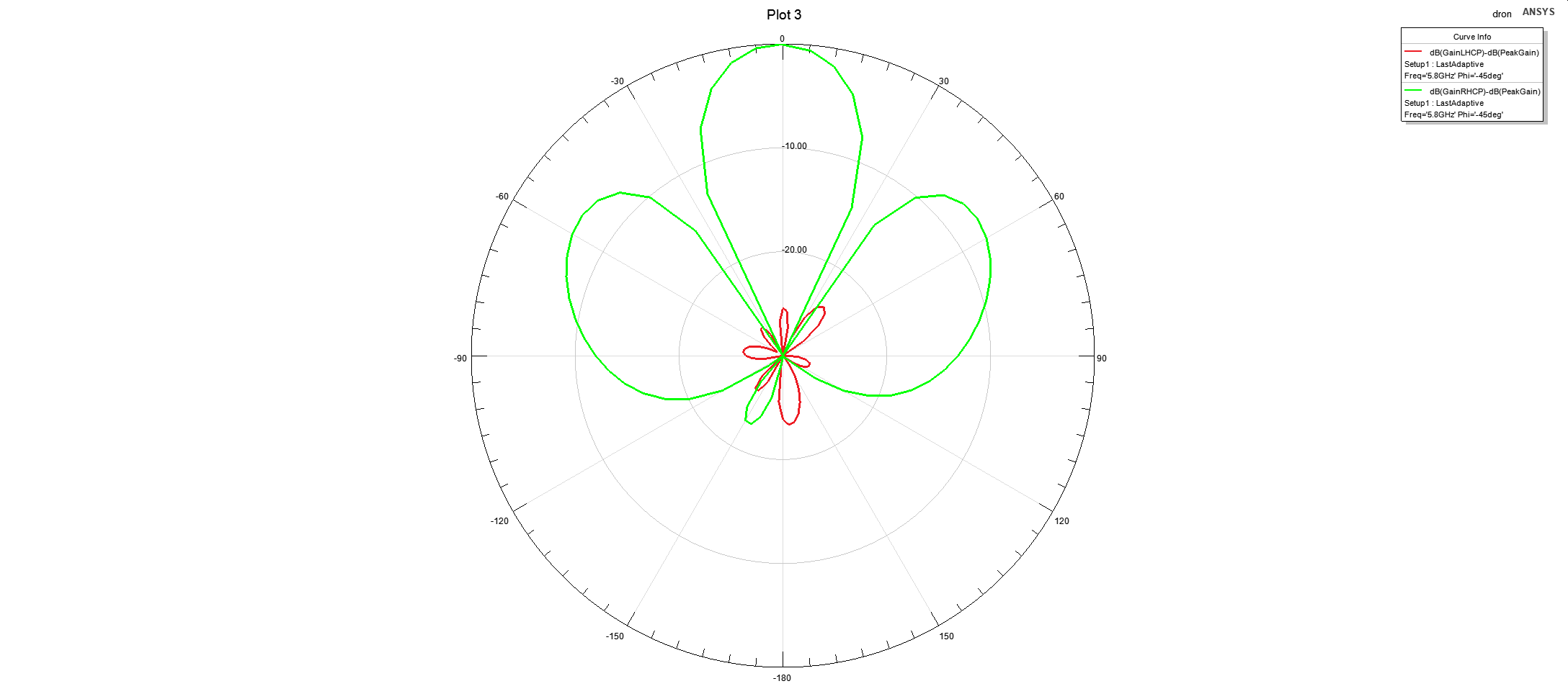
8 dBi patch with matching to 50 Ohm
on the upper side of the cross transformed (100 Ohm lambda/4) to 200 Ohm to get back to 50 Ohm matching
The cut in the patch element is for correct placement (avoid wrong rotation)
-
 1 person likes this
 -
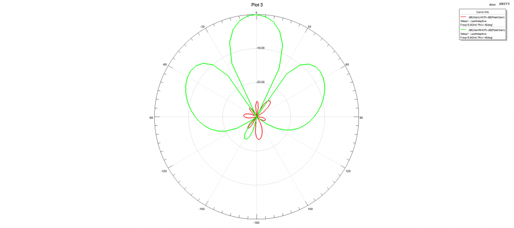
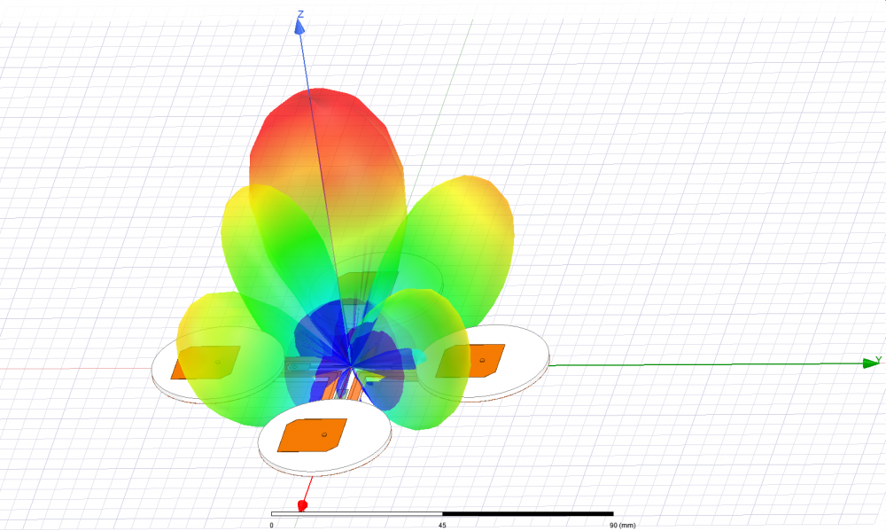
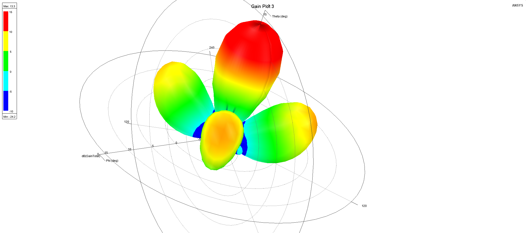
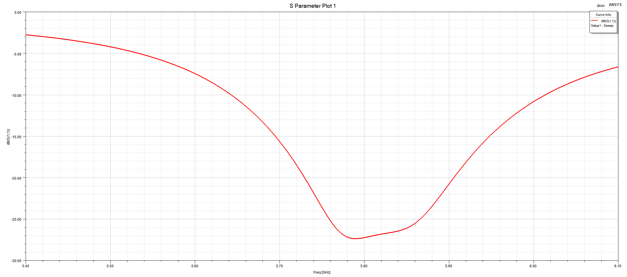
Drone like antenna

 1 person likes this


in Buy / Sell / Exchange
Posted
Update,
Today I replaced an old front end and got additional 1.5~2 dB.
The old one had an improvised shielding